What is grounding, what are its types, why is it made and how to protect against electrical leaks? Discover TT, IT, TN systems with operation, protection and function grounding with this article in a simple and understandable way.
The safety of electrical systems is important enough to save lives. "Grounding," which sits at the center of these systems, is an element that is often unnoticed but equally critical. For electrical installations found in every structure—from homes to industrial facilities—to operate correctly and not endanger human life, grounding systems must be installed correctly and checked continuously. In this article, we will discuss what grounding is, why it is done, and which systems are used to implement it in a simple and understandable way.
Grounding is a system that ensures the safe transfer of electric current to the earth. Its purpose is to protect people, animals, and other equipment against the risk of electric shock and fire in the event of any malfunction in electrical devices or systems.
When grounding is not performed or is done incorrectly, the metal surfaces of devices can remain under voltage, creating a vital risk for anyone who comes into contact with them. Such voltages are called "touch voltage" or "step voltage." It is mandatory to perform grounding in electrical installations to protect personnel in businesses and anyone who might come into contact with the devices.
The effects of 50Hz alternating current passing through the human body are as follows:
In electrical systems, grounding is divided into two categories: operational grounding and protective grounding. Operational grounding is the grounding of active electrical parts that are under voltage. This prevents the formation of overvoltage on electrical installations. Protective grounding, on the other hand, is the connection of metal parts—which are not normally under voltage but could become energized due to a fault—to the earth via a conductor.
The purpose of operational grounding is to prevent the formation of overvoltages on electrical installations by keeping the potential of the operating current circuit against the earth at a specific value.
Operational grounding is performed by connecting the star point of a transformer to the earth with a conductor. This prevents the occurrence of two-phase-to-ground faults and ensures that circuit breakers trip immediately. The star points and poles of high voltage (HV) and low voltage (LV) windings belonging to generators and power transformers are connected to operational grounding.
The resistance of operational grounding is approximately 2 Ω. In networks where the zero (neutral) point is grounded and protective grounding is performed, the resistance of the operational grounding can be found using the following formula:
$$R_0 = \frac{65\text{ V}}{\text{Breaking current of the largest grounded receiver}}$$
Note: If it is accepted that the current allowed to pass through the human body without endangering human life is 20-25 mA, the dangerous limit voltage in low voltage installations is concluded to be
$$ U_t = 65\,\text{V} $$
[GROUNDING IN ELECTRICAL INSTALLATIONS, Prof. Dr. Mustafa BAYRAM]
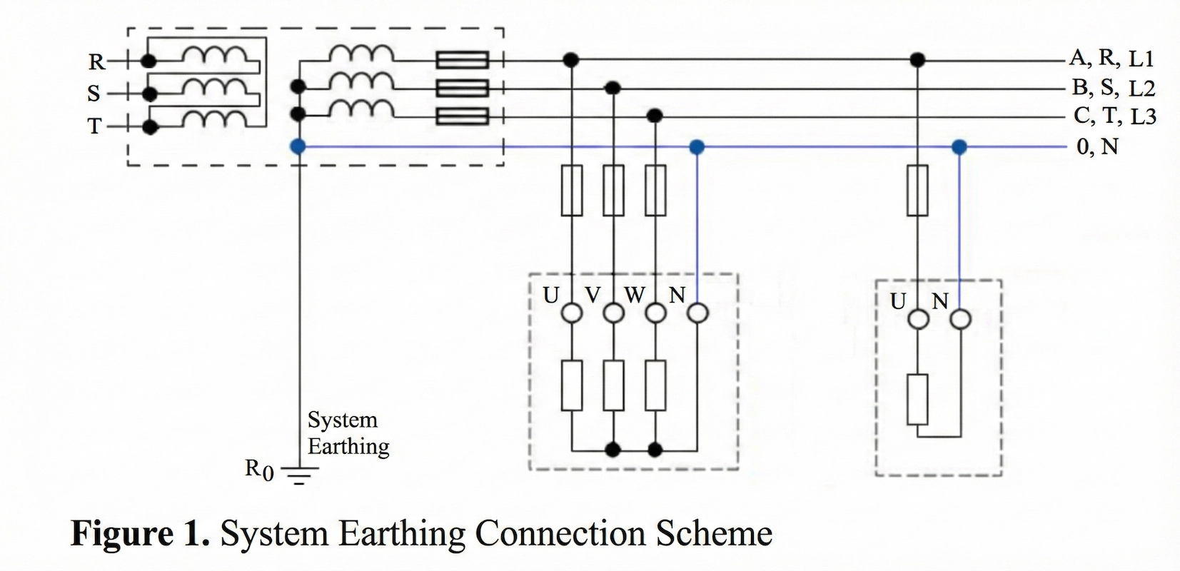
The schematic representation of operational grounding is provided in Figure 1.
It is the process of connecting metal parts—which are not under voltage under normal conditions but are anticipated to become energized due to any fault—to the earth with the help of a conductor.
The purpose is to protect people using electrical devices and animals against dangerous touch and step voltages. The protective grounding connection diagram is provided in Figure 2.

The points to be observed in the electrical installation while performing protective grounding are determined within the scope of electrical regulations. In protective grounding, all grounds within the facility are connected to each other. Voltage differences that may occur between any two points within the facility are prevented, and equipotentiality is ensured at all points.
Thanks to the equipotential busbar, there is no need for separate grounding; all new devices and panels to be added to the system can be connected to the equipotential grounding conductor.
The following parts are connected to the equipotential earth busbar for protective grounding:
If protective grounding is performed, in the event of any fault, the energy is cut off or dangerous currents flow to the ground, ensuring the system reaches its normal potential. In the event of any fault, the protective grounding resistance of the operating equipment—which is protected as a result of the ground contact completing the current circuit through the ground—must satisfy the following condition:
$$R_k \le \frac{65\text{ V}}{I_a}$$
For a transformer, there are two types of grounding: protective grounding serving to protect the transformer body, and operational grounding brought down to the ground from the transformer's star point.
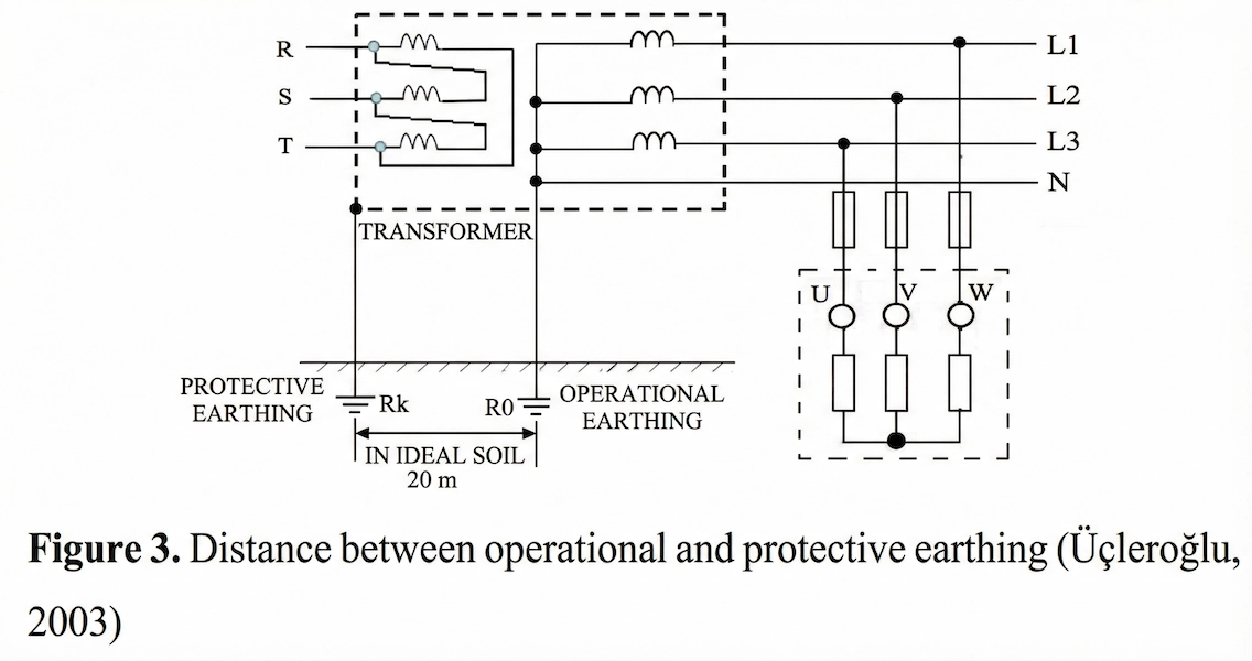
There must be a distance of 20 meters in ideal soil between protective and operational grounding. The schematic representation suitable for this is provided in Figure 3.
However, grounding the star point (neutral) only from the star point is not sufficient. Because if the operational grounding conductor breaks or if loosening occurs at the connection point, protection is disabled. Consequently, life and property safety cannot be ensured. To prevent this situation, the neutral conductor must be grounded at several more places.
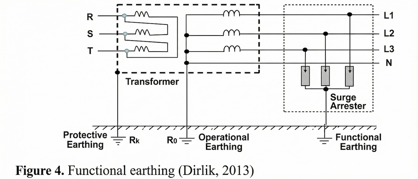
Functional grounding is a type of grounding performed—apart from operational and protective groundings—to enable a transmission facility or an element belonging to a business to fulfill its desired functions.
Additionally, it is the grounding performed for protection against lightning effects, rail systems, communication facilities, and LV (Low Voltage) devices. The schematic representation where operational, protective, and functional grounding are present together is provided in Figure 4.
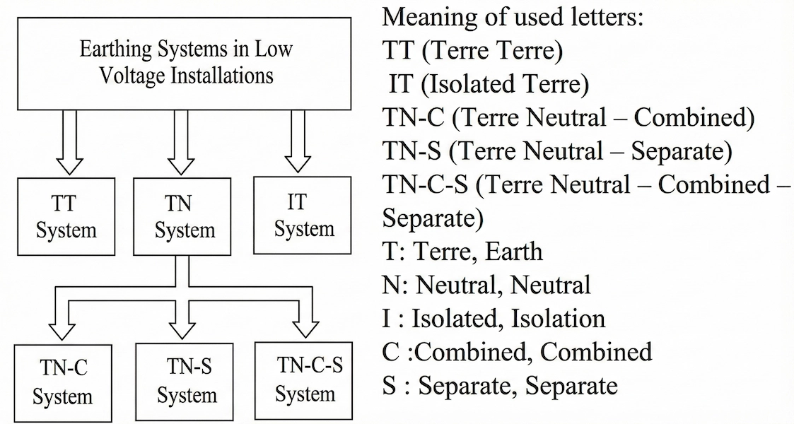
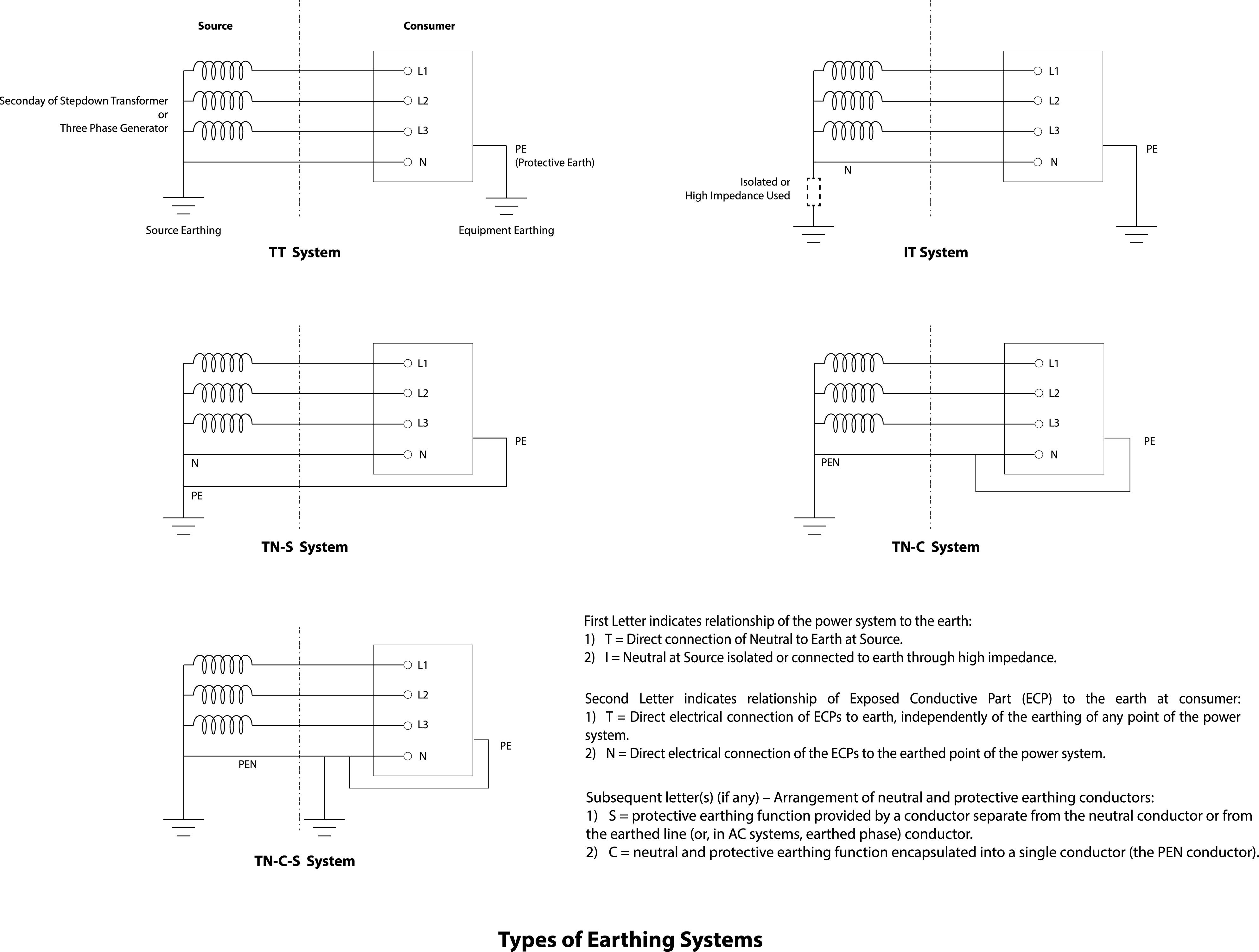
According to the Regulation on Grounding in Electrical Installations, electrical distribution networks in electrical facilities are classified into grounding systems as follows:
The TT Grounding System is a system where the star point (neutral) of the transformer is directly connected to the earth, and the bodies of electrical devices are connected to protective grounding.
In the IT grounding system, all live parts (parts under voltage) are isolated from the earth or connected to the earth at one point through an impedance. Exposed conductive parts in the electrical installation are grounded individually or collectively, or connected to the operational grounding. None of the live conductors are directly connected to the earth. Where connection to the earth is necessary, it must be done through a high-value impedance of at least 15 kΩ.
In the TN grounding system, there is a directly grounded point. Exposed conductive parts of the installation are connected to this point with the help of a protective conductor. Here, every exposed conductive part in the installation must be connected to the main earthing terminal of the installation via the protective conductor. Additionally, this terminal must be properly mounted to the grounded point of the power source.
TN grounding systems are divided into three classes based on the status of the protective (PE) and neutral (N) conductors: TN-C, TN-S, and TN-C-S.
In the entire grounding system, the neutral and protective functions are combined in a single conductor. All exposed conductive parts of the installation are connected via the PEN conductor.
The TN-C grounding system is generally not recommended. In the case of a star connection of the secondary windings of a three-phase transformer, the current passing through the neutral conductor is the vector sum of the currents passing through the phase conductors. In a balanced three-phase system, this sum is zero, so no current flows through the neutral conductor (Aydın, 2015). However, in three-phase systems, current flows through the neutral line in the event of single-phase linear loads or unbalanced supply.
Note: In this system, since earth and neutral currents cannot be separated, RCDs (Residual Current Devices) are not allowed.
A separate protective conductor is used throughout the entire installation. The Neutral (N) conductor is run as insulated. The Protective Earth (PE) conductor is provided by using the metal sheath of the supply conductor or via a separate conductor.
In other words, in the TN-S grounding system, protective and neutral conductors are run separately throughout the installation. It is ensured that all exposed conductive parts of the installation are connected to this protective conductor via the installation's main earthing busbar (terminal).
The TN-S grounding system is suitable for large consumers having one or more HV/LV (High Voltage/Low Voltage) transformers for their own needs, and for installations close to electrical energy sources if the installation/equipment is adjacent to the power source (transformers).
Neutral and protective functions are combined in a single conductor in a part of the system. In the TN-C-S grounding system, protective and neutral conductors are used separately in one part of the network and as a common conductor in another part.
It is ensured that all exposed conductive parts of the installation are connected to the PEN conductor via the installation's main earthing busbar. The Neutral (N) and protective (PE) conductors are combined at the grounding busbar.
To avoid risking human lives and the service life of devices against the risk of electrical leakage, it has become mandatory to perform foundation grounding in newly constructed buildings. Additionally, to eliminate the danger of system damage caused by potential electrical leakage or static electric charge accumulating on electronic devices in a building and main servers in data centers, the bodies of these devices must be connected to the foundation grounding with the help of a conductor. The effectiveness of equipotential bonding increases with the implementation of foundation grounding. It is also suitable for use as a grounding electrode in high-current and lightning protection installations and must be constructed in the form of a closed ring. The strips to be used for foundation grounding must be placed in the foundation section of the building's outer walls or within the foundation platform before the concrete is poured.
The ideal grounding process is completed with a lightning rod placed on the building after creating a Faraday cage, which is formed by repeating this process for the slab and column of each floor of the building.

Grounding resistance comes at the beginning of the most important issues to consider when performing grounding. Grounding resistance is defined as the resistance between the grounding electrode and the soil.
This resistance value is a variable that changes seasonally depending on the surface of the electrode and the type of soil. Every soil type exhibits a different resistance value against electric current. The specific resistance (resistivity) values of soil according to soil type are shown in the table below. One of the important factors to consider in the grounding system is ensuring that every point of the grounding electrode is in contact with the soil. Furthermore, to be able to state that grounding is done well, the grounding transition resistance (contact resistance) must be at the minimum level. The transition resistance of standard soil is around 10 Ω.
If the grounding resistance value exceeds the desired value, it must absolutely be lowered. While grounding is being done, attention should be paid to ensure the soil where the electrode will be buried has a low resistance value. However, soil with low resistance values may not always be available.
In such cases, a solution is found by burying the electrode in a location with low-resistance soil and extending the grounding conductor. Another solution is to dig a large pit where the grounding electrode will be buried and fill this pit with low-resistance soil.
To lower the grounding resistance, the following methods can be used: